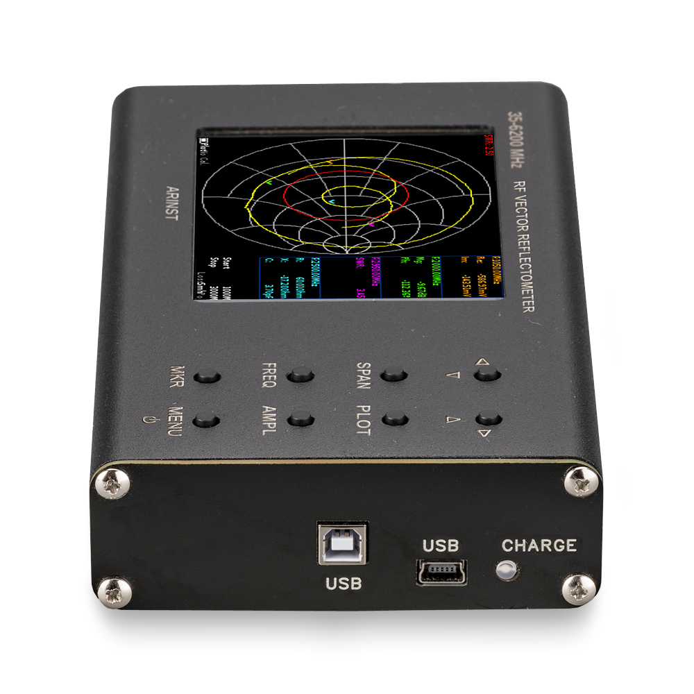
Portable vector network analyzer ARINST VR 23-6200
Print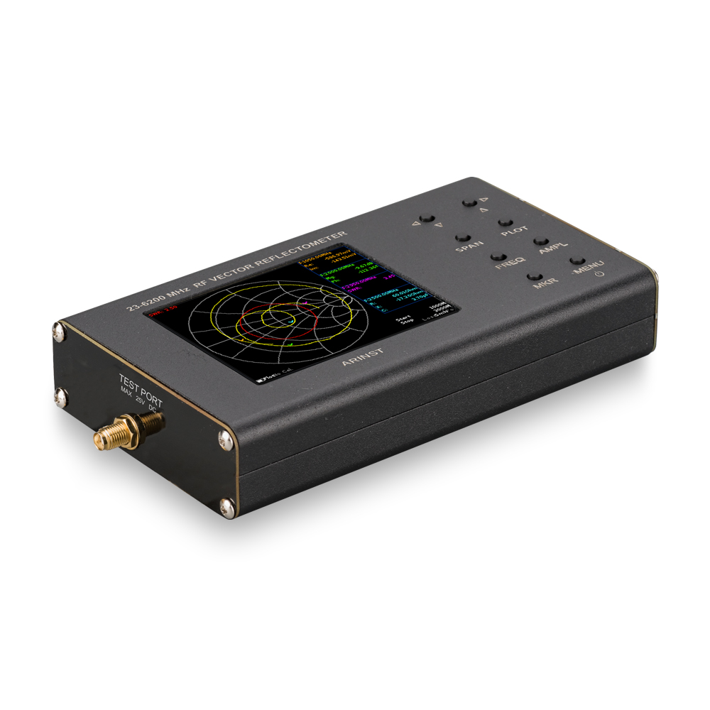


Frequency range 23-6200 MHz
Scan points 1000
Internal battery
Portable vector network analyzer (reflectometer) ARINST VR 23-6200 MHz is designed to measure the matching characteristics of passive and active radio devices (antennas, cables, filters, attenuators, amplifiers, etc.).
The device allows you to measure the parameters of the complex reflection coefficient, standing wave ratio (SWR), impedance, admittance, magnitude, phase, loss and distance to fault in the cable.
Purpose
VNA ARINST VR 23-6200 is made in a durable aluminum casing in the form of mobile autonomous instrument and is primarily intended to work directly on the object, as with low weight and compact dimensions has a low energy consumption. The analyzer will be especially useful to companies working in telecommunications, engaged in the installation and maintenance of antennas, in the amplification of cellular communication, etc. With it, service centers and repair crews can carry out RF analysis cable and antenna when carrying out commissioning or repair work. In addition, the device is ideal for workshops, radio amateurs, educational institutions and laboratories.
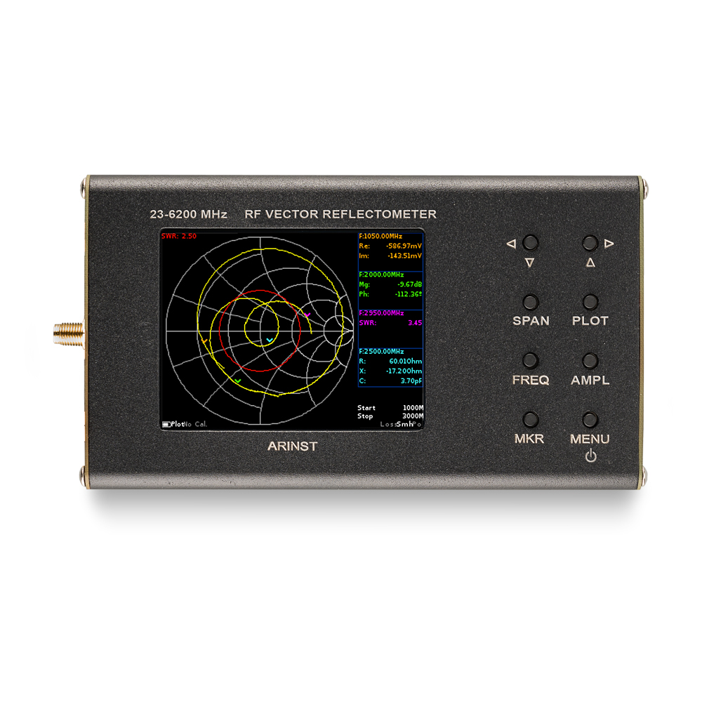
The device has a 3.2" color resistive screen to display the measurement results and control the device.
For example, you can use the instrument to do the following:
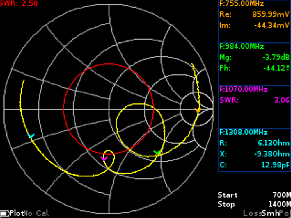
- To perform impedance matching using the Smith chart
- To measure the standing wave ratio
- To measure the attenuation in the cable
- To measure the distance to fault or irregularity in the cable
Advantages of vector network analyzer ARINST VR 23-6200 MHz:
- color touch screen with a diagonal of 3.2 inches allows for quick configuration of the scan parameters and display of measurement results
- wide operating frequency range: 23 to 6200 MHz
- high scan rate of 1000 points/s
- high precision of measurement: 0.25 dB and 1.5° over the entire frequency range
- the ability to display up to four independent markers on all charts, allowing an accurate assessment of the measured parameter
- display almost all possible interpretations of the reflection coefficient
- the ability to measure the distance to fault and loss in the cable
- small weight and dimensions: 400 grams with "pocket" dimensions 155×81×27 mm
- built-in battery provides up to 2 hours of battery life
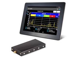
- ability to power the device from a tablet or smartphone via USB OTG cable: not in time discharged battery will not stop the workflow
| SPECIFICATIONS ARINST VR 23-6200 MHz: | ||
|---|---|---|
| Operating frequency range | 23-6200 MHz | |
| The frequency resolution | 10 kHz | |
| Maximum number of scan points | 1000 | |
| Scanning rate | 1000 points/s | |
| The direction of the bridge, uncorrected throughout the range | >12 dB | |
| Directivity effective (after full single-port calibration)1 | >50 dB | |
| The standing wave ratio at the input | <2 | |
| Phase measurement precision1 | >1.50 | |
| Magnitude measurement precision1 | >0.25 dB | |
| Resolution determining the distance to fault2 | (C x VF)/2S m | |
| The maximum length of the measured cable3, with VF =1 | 3000 m | |
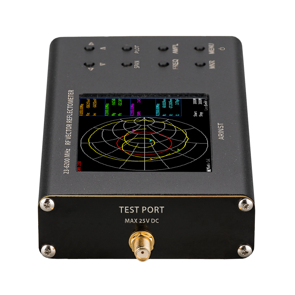
| Maximum DC input voltage | 25 V | |
| Displayed graphs | the Smith chart; polar chart; the phase of the reflection coefficient; magnitude; logarithmic magnitude; VSWR, distance-to-fault; cable loss | |
| Operating temperature range | 0...+400С | |
| Screen diagonal | 3,2" | |
| Screen type | touch resistive |
|
| Screen resolution | 320х240 | |
| Battery capacity | 2500 mAh | |
| Continuous battery life4 | ~2 h | |
| Battery charge time | ~6 h | |
| Overall dimensions (L×W×H) | 155×81×27 | |
| Weight | 0.4 kg | |
1 The measurement is performed after warming up the device for at least five minutes with a full (short, open, load) single-port calibration. The change in ambient temperature from the time of calibration to the time of measurement shall not exceed ±3 °C.
2 Where C is the speed of light m/s; VF is the speed factor (the ratio of the speed of propagation of the electromagnetic wave in the cable to the speed of propagation of the electromagnetic wave in vacuum), takes a value depending on the cable from 0.1 to 1; S is the scanning frequency range in the frequency reference (Hz).
3 Depends on the amount of attenuation in the cable and is the limit of the display.
4 At ambient temperature plus 20±5°C after full charge.
Smith diagram for GSM antenna (900 MHz)

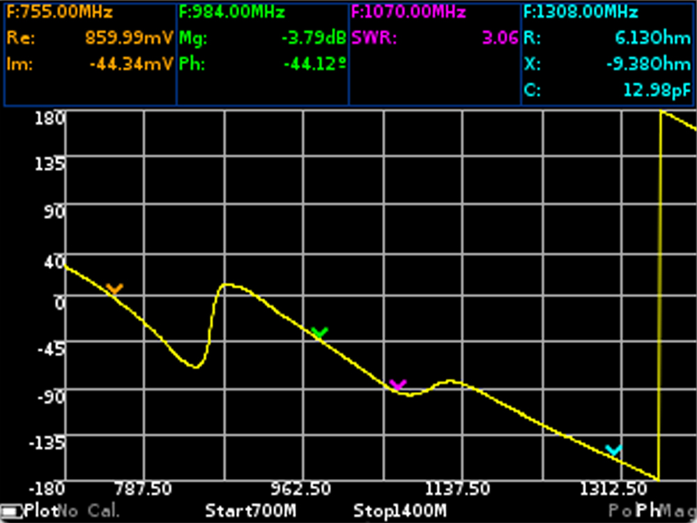
The phase of the reflection coefficient for antenna GSM

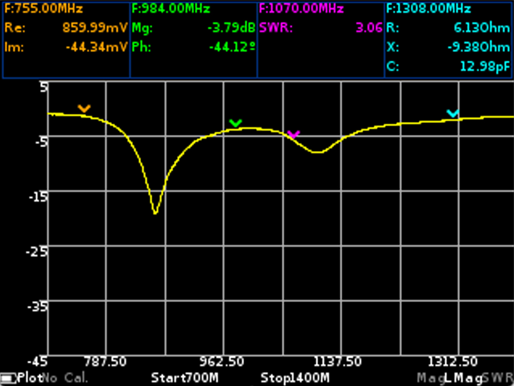
The logarithmic magnitude of the reflection coefficient for antenna GSM

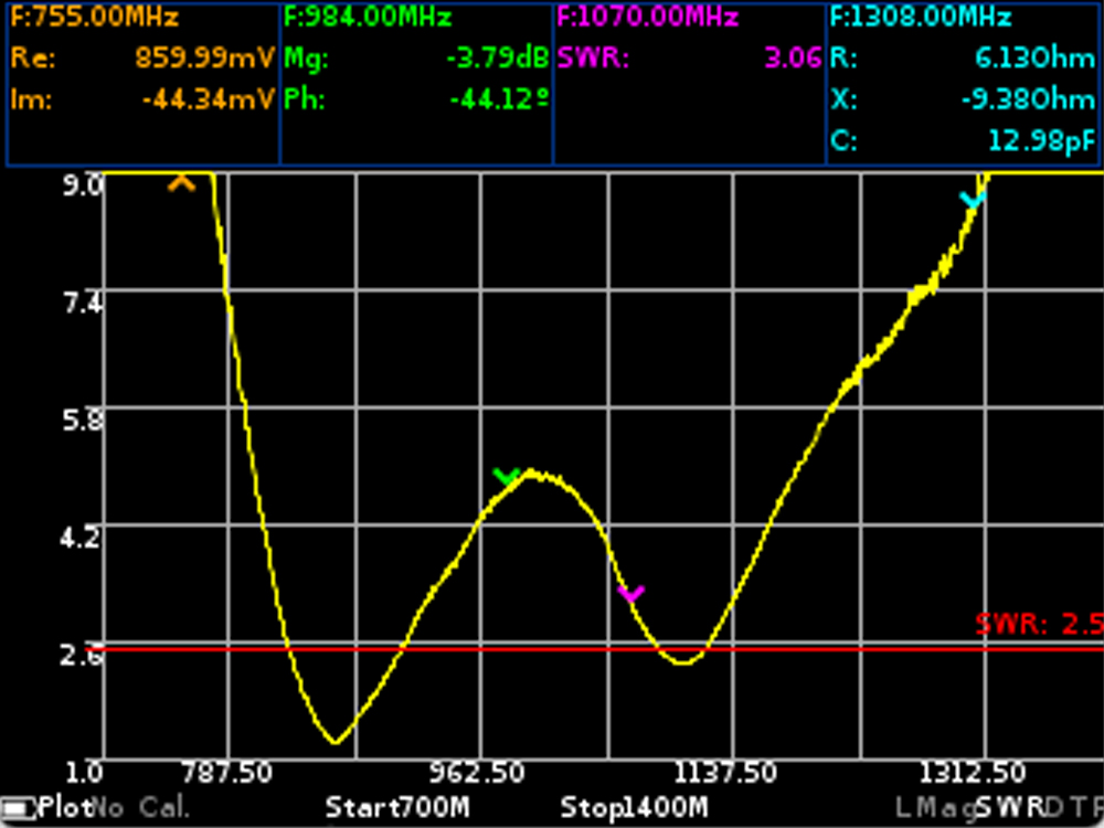
Standing wave ratio of GSM antenna

A graph measuring the distance to a cable fault

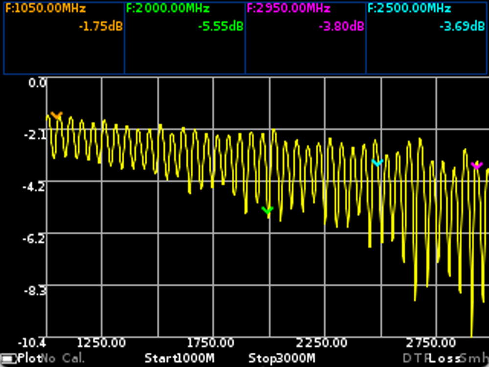
Graph of measurements of the attenuation in the cable

The device has a factory calibration, the device connector is taken as the reference plane. If you plan to carry out measurements using cable assemblies, adapters, etc., then you will need to recalibrate. To do this, use the 50 Ohm calibration kit SOL (S- Short Standart - O -Open Standart L - Matched Load). SOL calibration kits are most often found in the N-type and SMA-type form factors. Choose the form factor corresponding to the type of connector, on the reference plane of which calibration is planned.
|
Dimensions (length , width , height ), mm
|
155
x
81
x
27
|
Equipment:
|
Position
|
ARINST Vector Reflectometer 23-6200 MHz
|
|
USB connection cable
|
||
|
Passport
|
||
|
Package
|
||