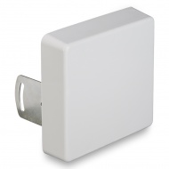
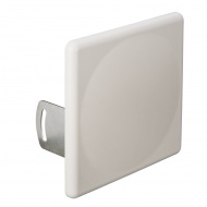
MIMO antenna supports standards LTE1800, UMTS2100, Wi-Fi 2400, LTE2600.
The gain of 12-15 dB. For all operators.
Recommended for use with 3G/4G modems and routers.

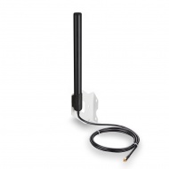
Broadband antenna 2G/3G/4G/WIFI. The gain of 12-15 dB.
It is recommended to use complete with 3G/4G modems and GSM1800/3G repeaters.

Broadband external antenna with gain 15 dB, frequency ranges 790-960 MHz and 1700-2700 MHz

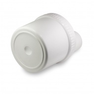
Antenna for terminals. Gain 6 dB.
For all operators.
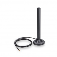
Gain up 3dB (800MHz) to 6 dB (2600MHz).
Includes RG58 cable, length 3 meters.
Works with all mobile operators. The amplification - 18 dB.
Supports standards LTE1800, UMTS2100, LTE2600 and WiFi(2.4 GHz) 802.11 b/g/n with MIMO technology.
Amplification up to 35 dB.
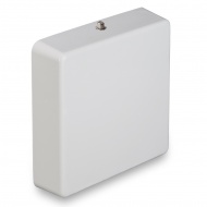
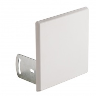
Compact antenna with band 800-960 MHz, 1710-2170 MHz for indoor installation in conjunction with a repeater 900/1800/2100 MHz.
Broadband MIMO antenna for 2G/3G/4G/WIFI. The amplification - 18 dB.
Supports standards LTE1800, UMTS2100, WiFi2400, LTE2600.
It is recommended to use complete with 3G/4G modems and routers.
Gain 14 dB, standards: DCS-1800, 3G (UMTS 2100)
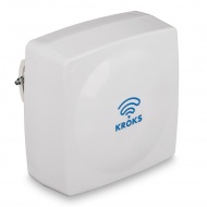
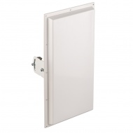
Широкополосные антенны КАА15-1700/2700 U-BOX и КР15-750/2900 U-BOX с усилением 15 дБ совмещенные с гермобоксом. Предназначена для передачи и усиления мобильного сигнала стандартов:
- 3G (UMTS 2100), 4G (LTE 1800, LTE 2600), YOTA, Wi-Fi 2400 — для модели КАА15-1700/2700 U-BOX;
- 2G (GSM 900, GSM 1800), 3G (UMTS 900, UMTS 2100), 4G (LTE 800, LTE 1800, LTE 2600), YOTA, Wi-Fi 2400 — для модели КР15-750/2900 U-BOX.
Корпус антенны является гермобоксом, в котором можно разместить роутер или 3G/4G модем. В гермобоксе размещается любой из роутеров Kroks для гермобокса или роутеры других производителей.
Portable spectrum analyzers series Arinst SSA is intended to display the spectra of signals in the frequency range from 35 to 6200 MHz. The instrument allows to determine the amplitude and frequency of spectral components included in the signal.
Spectrum analyzers show spectra of signals of all common technologies: wifi, 2G, 3G, 4G, LTE, CDMA, DCS, GSM, GPRS, GLONASS, etc.
GSM900 antenna for interiors with wide beamwidth.