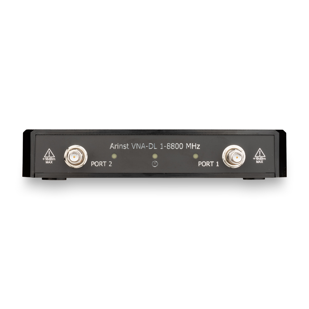
ARINST VNA-DL 1-8800 MHz two-port vector network analyzer
Print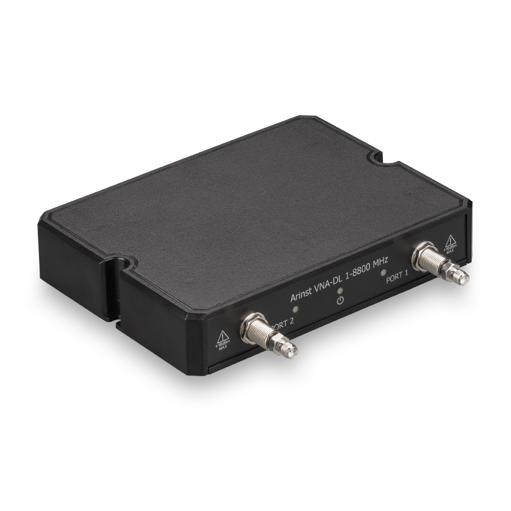


Frequency range 1 - 8800 MHz
Measurement of parameters S11 and S21
Two measurement ports
Scan points 1000
Variable IF bandwidth 20 Hz - 1 kHz
The dynamic measurement range of the transmission coefficient is more than 80 dB
Ability to save presets and tracks (Touchstone)
Up to 4 charts on one screen
Compact size
Desktop form factor
Товар добавлен в корзину
Software for device download here.
For whom?
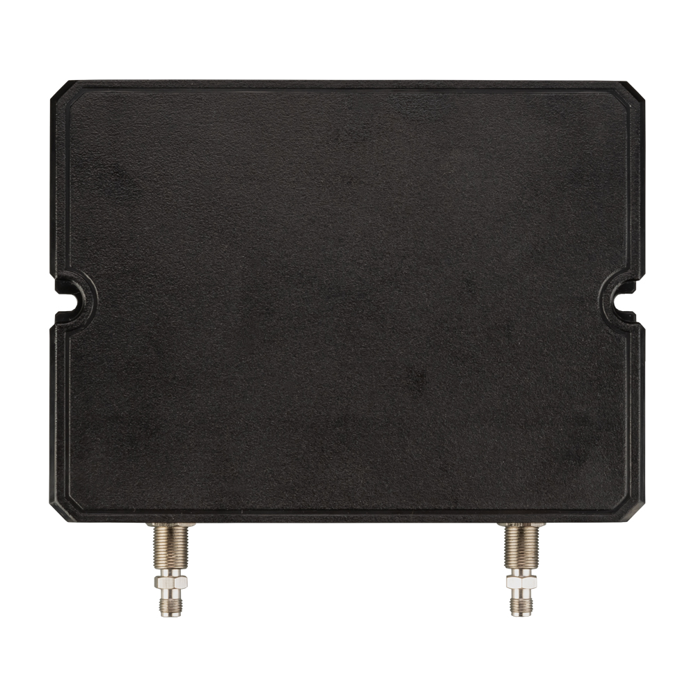
The two-port vector network analyzer ARINST VNA-DL 1-8800 MHz is made in a plastic case in the form of a desktop device, designed to measure the parameters of various radio devices (antennas, filters, amplifiers, etc.) in the design and manufacture of telecommunications equipment. The device is ideal for workshops, radio amateurs, educational institutions, service centers. Requires a PC running Windows 7-10 to work. (Not included in the package).
Usage examples:
- Make impedance matching using a Smith chart
- Tune the antenna
- Measure standing wave ratio
- Measure the frequency response of passive and active devices
- Measure the phase response of passive and active devices
- Tune filters of the main selection, filters of the intermediate frequency
- Measure attenuation in cable, microstrip line, waveguide
- Measure the distance to the fault in the cable or its length
To calibrate the device, we recommend using ready-made calibration kits with N-type and SMA-type.
To avoid premature wear of the instrument connectors, we recommend taking measurements with the screwed-on adapters supplied.
Advantages of the ARINST VNA-DL 1-8800 MHz two-port vector network analyzer:
- wide operating frequency range: from 1 to 8800 MHz
- maximum scanning speed - 500 points / s
- high precision in measuring the reflection coefficient: 0.25 dB and 0.7° in the entire frequency range
- display of almost all possible interpretations of reflection coefficient and transmission coefficient
- the ability to measure the distance to fault and loss in the cable
- saving user presets and measurement results-traces (in Touchstone format)
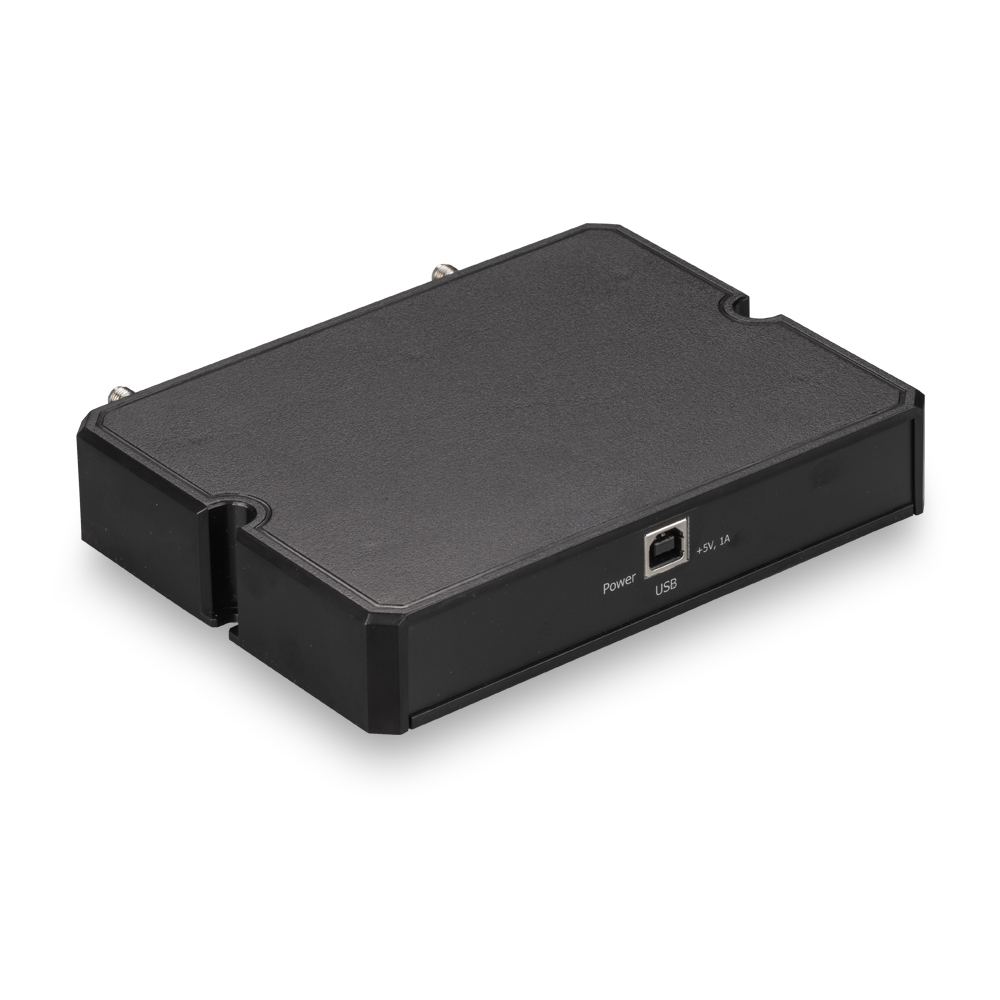
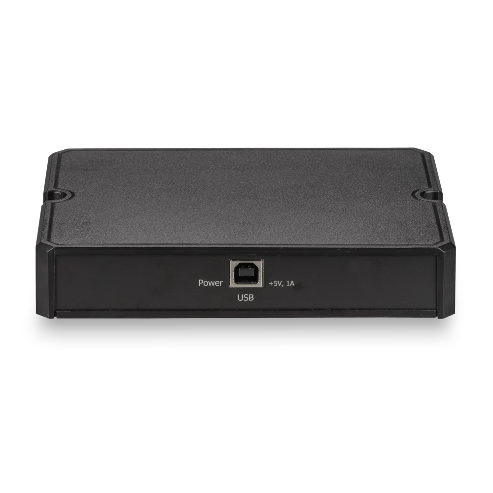
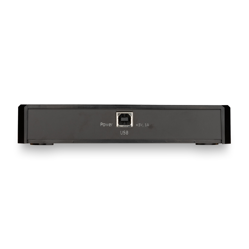
- power supply and control of the device via the USB port of the PC
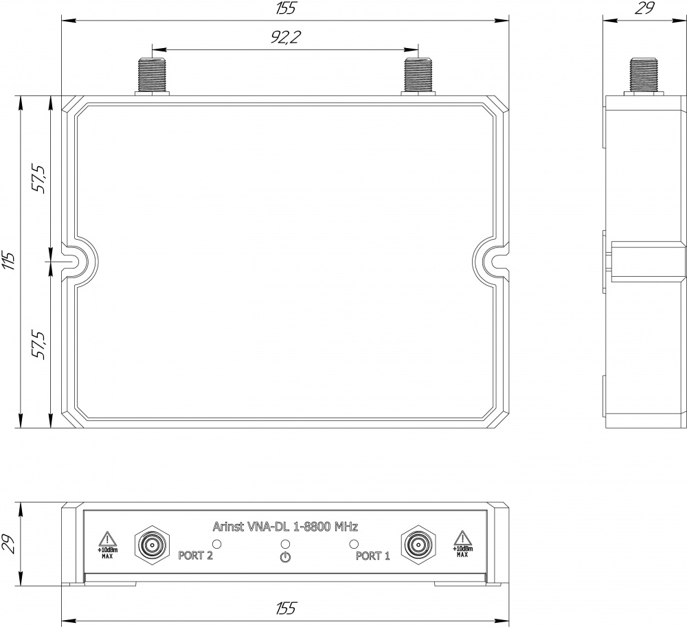
- low weight and dimensions: 250 grams , 155×127×29 mm
| Technical characteristics ARINST VNA-DL 1-8800 MHz | |||
| Working frequency range | 1 - 8800 MHz | ||
| Frequency resolution | for frequencies 1-140 MHz | 100 Hz | |
| for frequencies 140-8800 MHz | 10 kHz | ||
| Maximum number of scan points | 1000 | ||
| Scanning speed for one channel (BW = 1 kHz) | 500 points/s | ||
| Dynamic range S21 (BW=20 Hz) | for frequencies 1-4000 MHz | >80 dB typ. 85 | |
| for frequencies 4000-6900 MHz | >75 dB typ. 80 | ||
| for frequencies 6900-8800 MHz | >65 dB typ. 75 | ||
|
Bridge directivity uncorrected across the entire range, not less |
12 dB | ||
|
Effective directivity 1 (after a full single-port calibration), not less |
55 dB | ||
| Input standing wave ratio, no more | 2 (1.3 typ.) | ||
| Phase measurement precision1, no more | 0,7о | ||
| Magnitude measurement precision1, no more | 0,25 dB | ||
| Resolution of determining the distance to the fault2 | (C x VF) / 2S м | ||
| Maximum length of the measured cable3, when VF=1 | 3000 m | ||
| Compensation of the electrical cable length, when VF=1 | ±3 m | ||
| Maximum DC Input Voltage | 25 V | ||
| Maximum input power supplied to ports | + 10 dBm | ||
| Maximum power of the probing signal, no more | -3 dBm | ||
| Displayed graphs | ■Smith chart; ■polar chart; ■phase of the reflection coefficient (RC) and phase of the transmission coefficient (TC); ■magnitude RC and TC; ■logarithmic magnitude RC and TC; ■SWR; ■distance to fault; ■cable loss; ■group delay time | ||
| The number of stored user settings | not limited | ||
| The number of stored traces | not limited | ||
| Working temperature range | 0 ... +40оС | ||
| PC connection interface | USB | ||
| Maximum current consumption, no more than | 1 А | ||
| Overall dimensions (L×W×H) | 155×127×29 mm | ||
| Weight | 0,25 Kg | ||
1 The measurement is performed after the instrument has warmed up for at least five minutes with a full two-port calibration. The change in ambient temperature from the moment of calibration to measurements should not exceed ±3 °С.
2 Where С - speed of light m / s; VF – the speed factor (the ratio of the speed of propagation of an electromagnetic wave in a cable to the speed of propagation of an electromagnetic wave in a vacuum), takes a value depending on the cable from 0.1 to 1; S – scanning frequency range (Hz).
3Depends on the amount of attenuation in the cable and is the indication limit on the display.
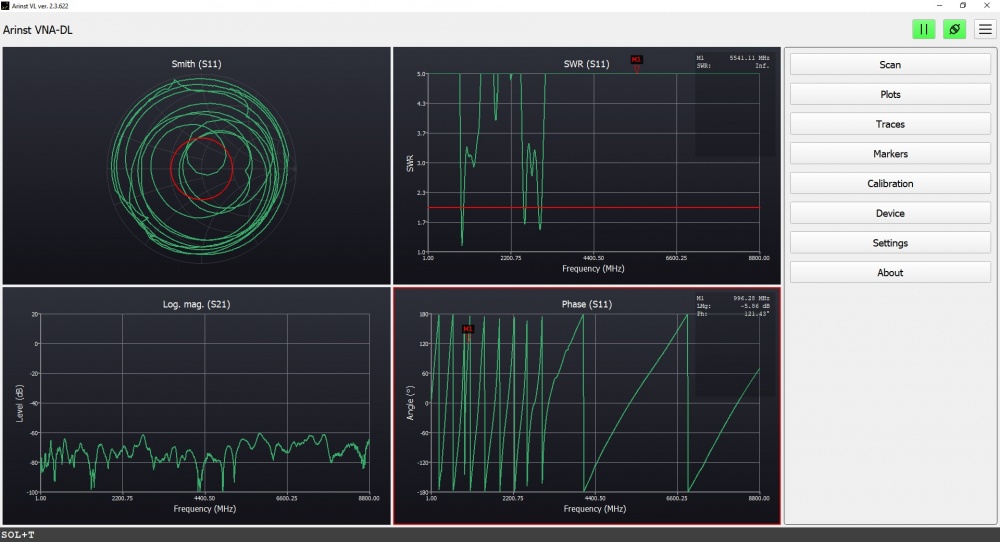
Diagrams and plots
Device control interface
Graphics menu item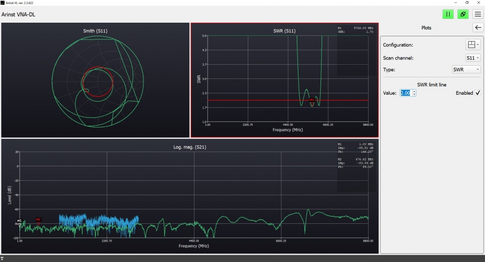
Calibration menu item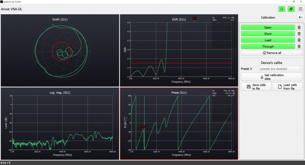
Tracks menu item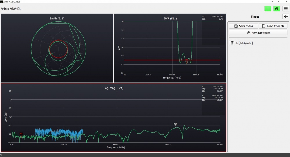
Markers menu item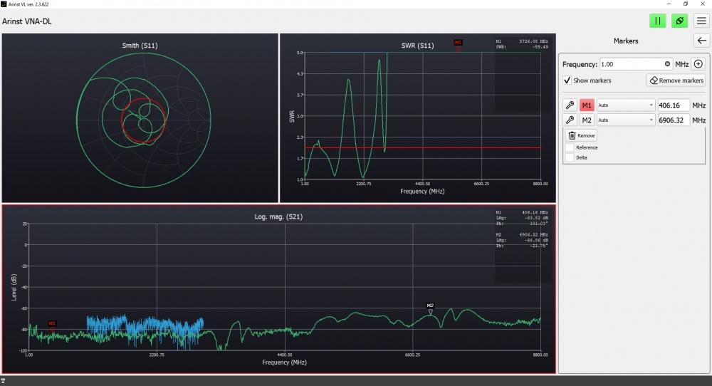
Scanning menu item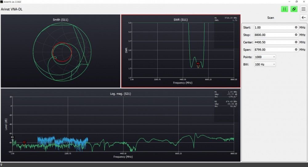
Low Pass Filter characteristics (LPF)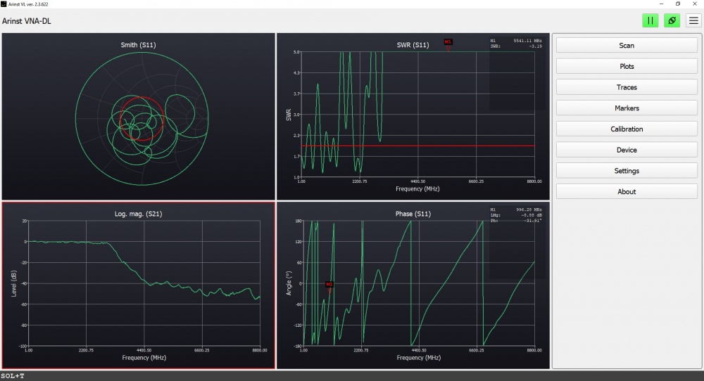
High Pass Filter characteristics (HPF)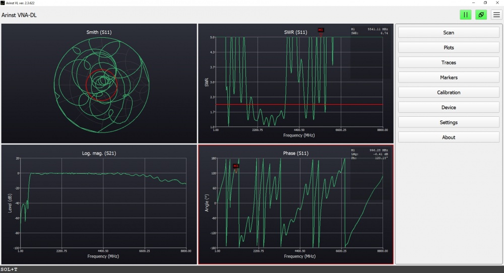
Bandpass filter characteristics (BPF)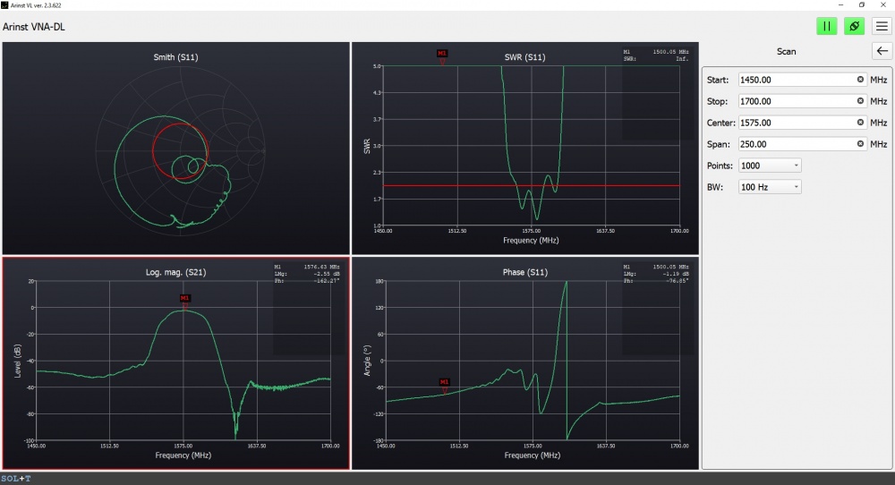
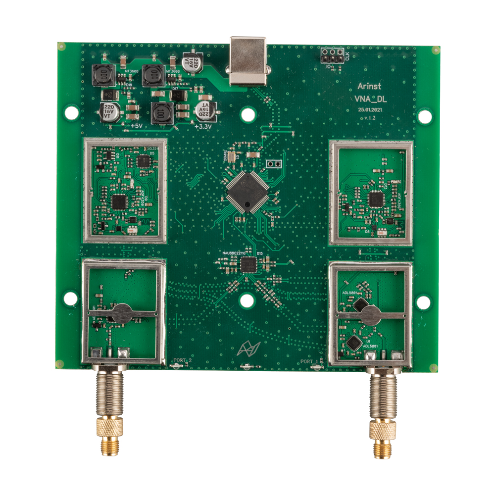
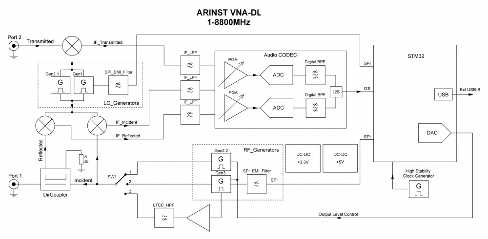
Block diagram of a two-port vector network analyzer Arinst VNA-DL 1-8800 MHz
|
Dimensions (length , width , height ), mm
|
155
x
127
x
29
|
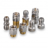
Equipment:
|
Position
|
Adapter SMA(female)-SMA(female), 2 pc
|
|
Package
|
||
|
Passport
|
||
|
Cable Double USB2.0(male)-A to USB2.0(male)-B, with data transfer, 120 cm
|
||
|
Analyzer
|
||