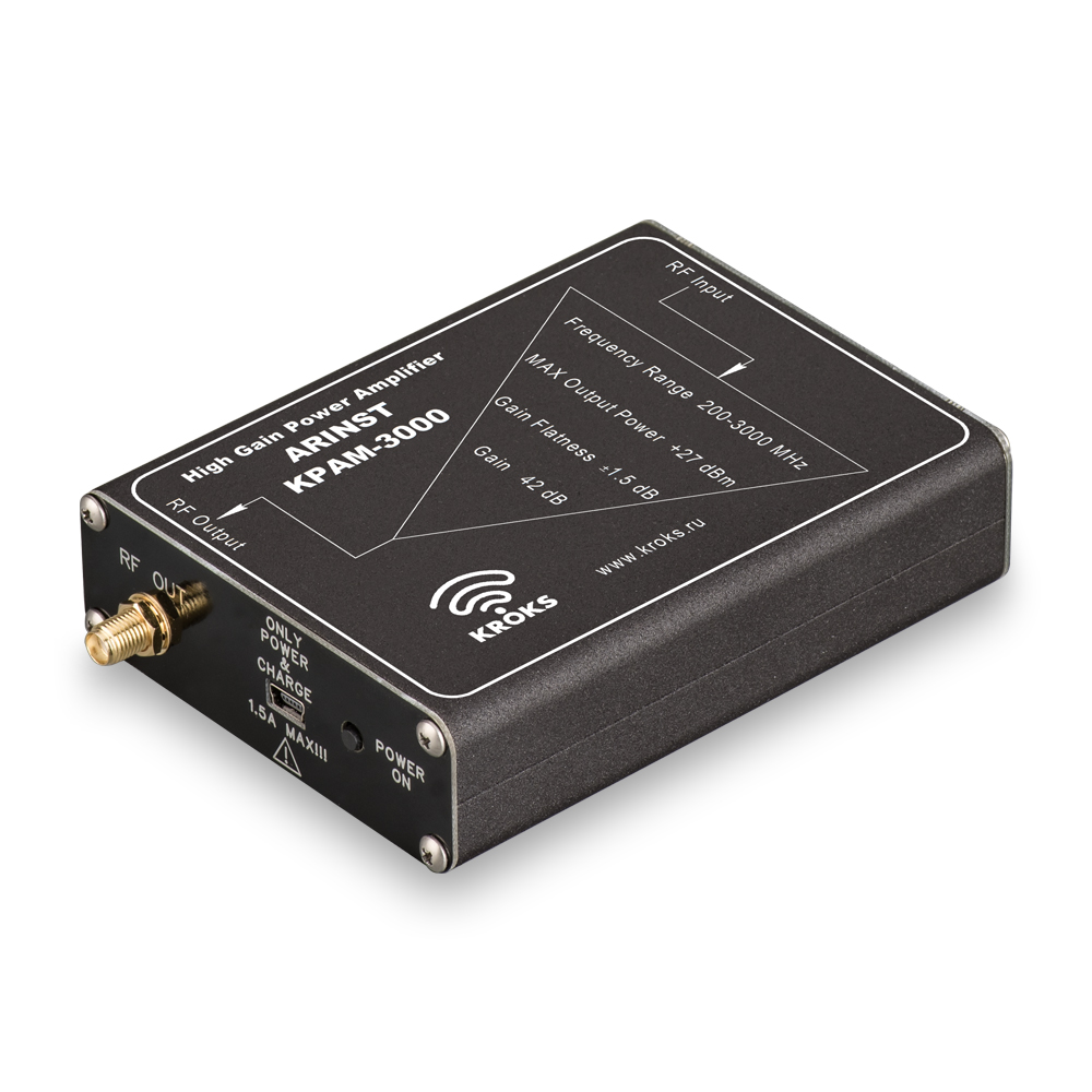
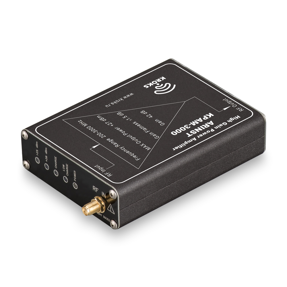
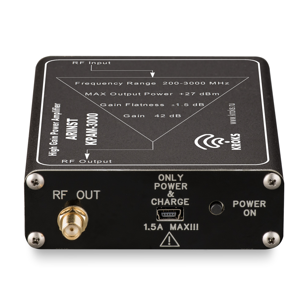
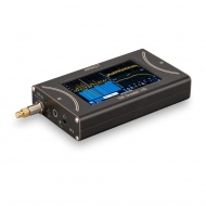
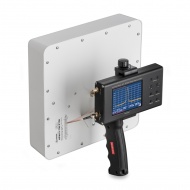
KPAM-3000 is designed to amplify the input high-frequency signal in the frequency range of 200-3000 MHz. The source of the high-frequency signal is a sweep generator of the spectrum analyzer, from which the signal is fed to the test device through a power amplifier. The amplifier is used in high-frequency signal amplification paths. The input power level must not exceed the value specified in the technical specifications of the device. The amplifier is powered by a built-in Li-Ion battery.
The power amplifier is designed to work in conjunction with spectrum analyzers Arinst that have a built-in tracking generator.
The power supply of the device is designed in such a way that the amplifier after switching on works only if there is a signal with input power from -25 dBm to -15 dBm. If the input signal is missing or is below -25 dBm, the device will automatically turn off. If the input signal is higher than -10 dBm, then the device may fail; such a case is not guaranteed.
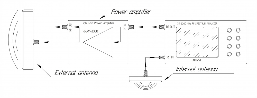
Measurement of isolation between antennas.
When installing cellular amplifiers (repeaters) sometimes there are problems associated with self-excitation of amplifiers. This is due to the output signal hitting the input of the amplifier, which causes oscillation. In oscillation mode, the amplifier interferes with the base station and may fail.
Also, there may be a problem of the echo signal resulting from the falling of the output signal of the amplifier at its input with a slight delay. This effect causes a decrease in the quality of communication, reducing the comfort of communication or making communication impossible. In order to prevent oscillation and echo, it is necessary to provide a sufficient level of electromagnetic isolation between the antennas at the input and output of the amplifier. The isolation between antennas is characterized by the ratio of the power received by one antenna to the power emitted by the other antenna.
The optimal value for decoupling between antennas should be 20 dB higher than the gain of the cellular amplifier (repeater) planned for installation. If the decoupling value is significantly lower, then additional work must be done to increase the decoupling value between the antennas (change the polarization, raise the external antenna, move the internal, etc.) to achieve the desired value.
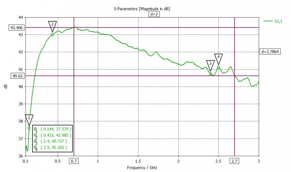
Diagram - typical amplitude-frequency characteristic of the power amplifier.
| TECHNICAL PARAMETERS OF KPAM-3000: | |
|---|---|
| Bandwidth | 200 — 3000 MHz |
| Maximum power output | + 27 dBm |
| Gain | 42 dB |
| Uneven frequency response in the band | ± 1,5 dB |
| Recommended input level | - 15 dBm |
| The minimum level of the input signal | - 25 dBm |
| Maximum short-time input level | - 10 dBm |
| Supply voltage | 5 V |
| Current consumption during battery operation | 0,8 ± 0,1 А |
| Current consumption when operating from the power supply in charging mode, not more than | 1,5 А |
| Supply current only in charging mode | 0,35 ± 0,1 А |
| Battery capacity | 2500 mА*h |
| Continuous battery life | ~ 2 h |
| Battery charging time | ~ 5 h |
|
Dimensions (length , width , height ), mm
|
124
x
81
x
27
|
Equipment:
|
Position
|
Power amplifier KPAM-3000
|
|
Mini-USB-USB charging cable
|
||
|
Pigtail SMA (male) - SMA(male)
|
||
|
User manual
|
||
|
Package
|
||
