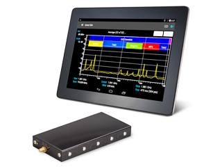
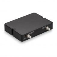
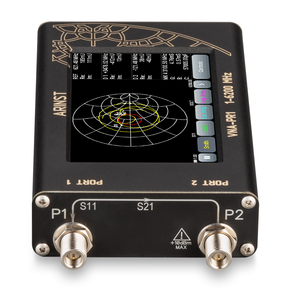
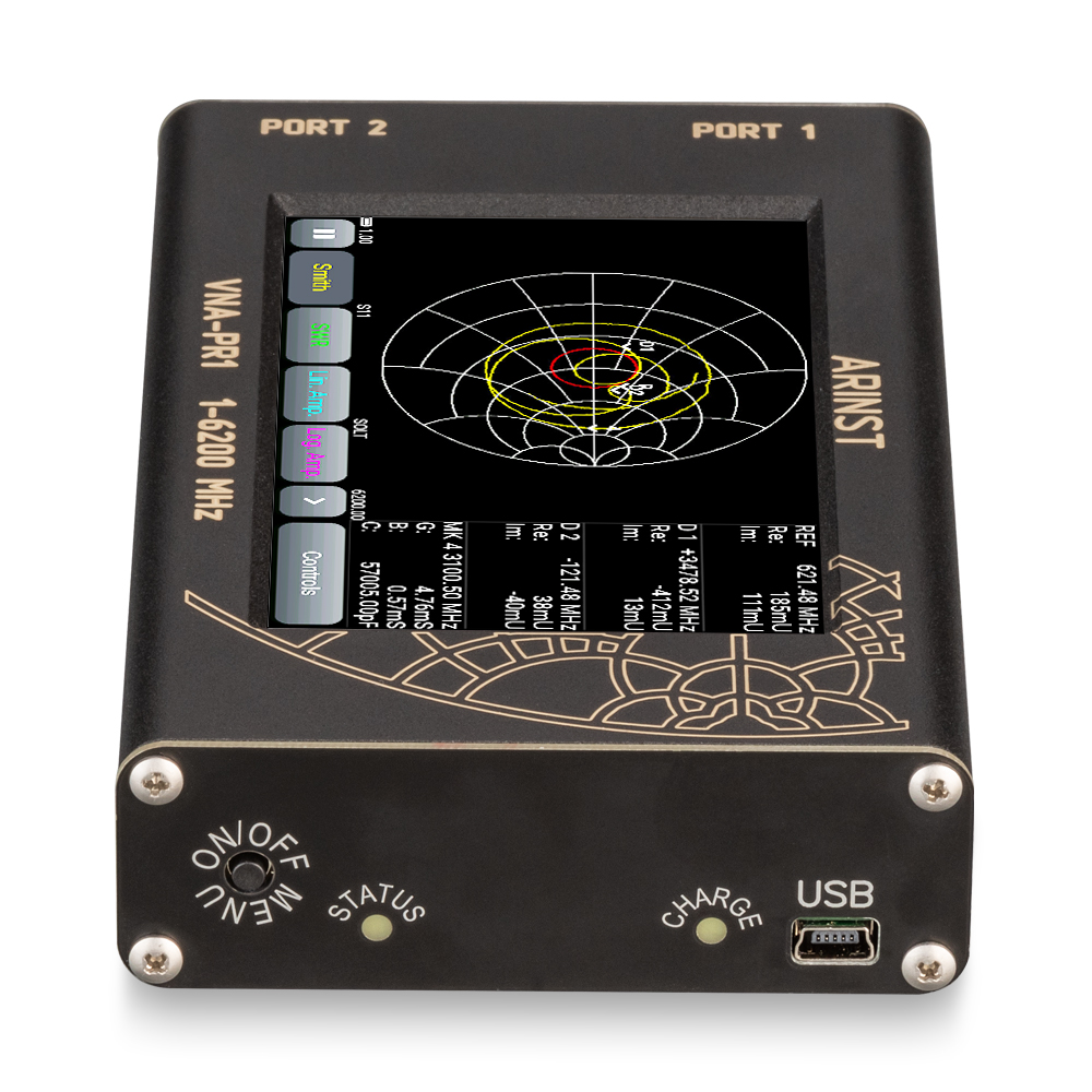
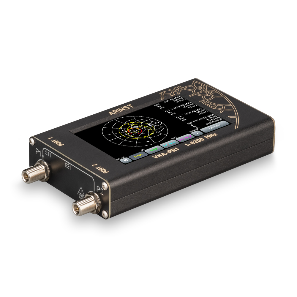
Portable 2-port vector network analyzer reflectometer Arinst VNA-PR1 1-6200 MHz
Print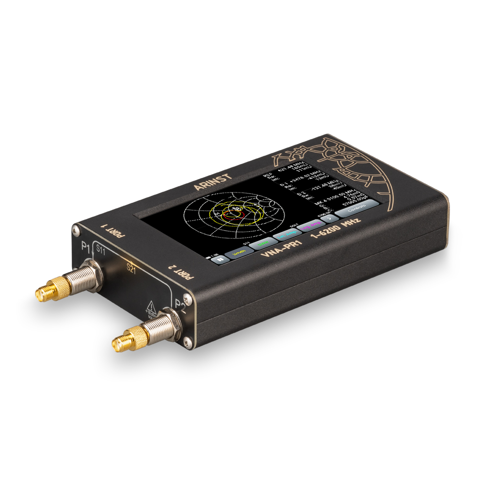


Frequency range 1-6200 MHz
Measuring parameters S11 and S21
The number of measuring ports - 2
The number of scan points - 1000
Saving 32 user presets and 32 measurement results – traces
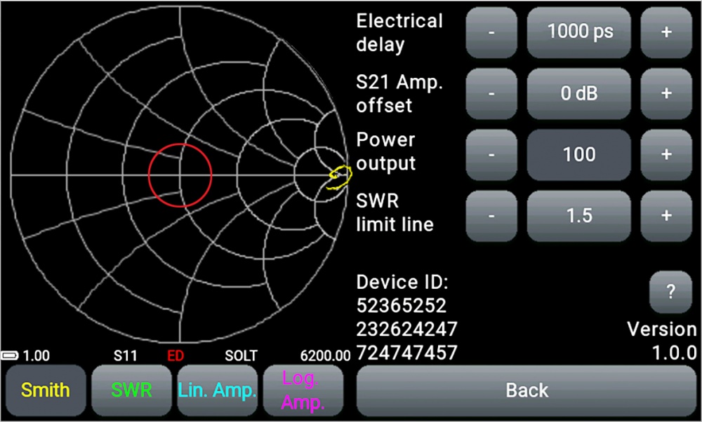
Ability to compensate for the electrical length of the cable
Adjusting the output power of the probe signal generator
Shift of the amplitude scale when measuring the frequency response of active devices and attenuators
Built-in 5000 mAh battery provides up to 2.5 hours of battery life
ARINST VNA-PR1 portable two-port vector network analyzer is designed to measure the matching characteristics of passive and active radio devices (antennas, cables, filters, attenuators, amplifiers), check the integrity of high-frequency cables, measure their parameters and other amateur radio measurements.
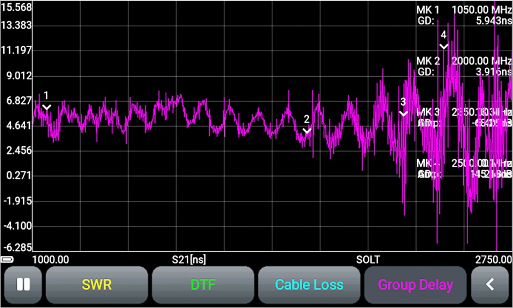
The device measures parameters S11 and S21, voltage standing wave ratio (VSWR), impedance, admittance, phase, group delay time (GD), losses and distance to cable fault.
For whom?
The ARINST VNA-PR1 analyzer is made in a robust aluminum case in the form of a mobile device with autonomous power supply and is intended primarily for work directly on the site, since it is characterized by low power consumption with its low weight and compact size. The analyzer will be especially useful for telecommunications companies that install and maintain antennas, amplify cellular communications, etc. It can be used by service centers and repair teams to perform RF analysis of cables and antennas on-site during commissioning or repair work. In addition, the device is ideal for workshops, radio amateurs, educational institutions and laboratories.
The device has a 4-color resistive screen for displaying measurement results and controlling the device.
For example, using the device, you can perform the following work:
- Perform impedance matching using the Smith diagram
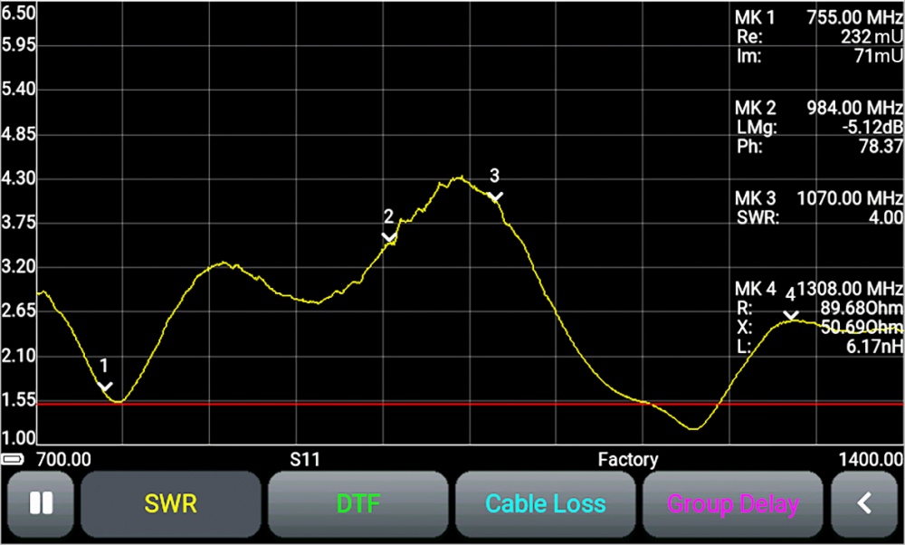
- Measure the standing wave coefficient
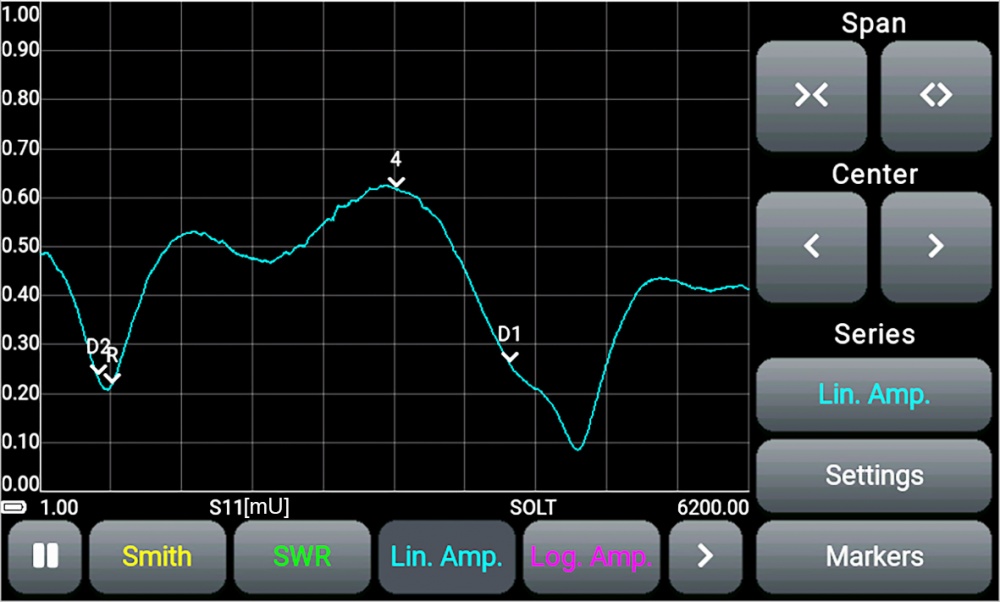
- Measure the frequency response of active devices
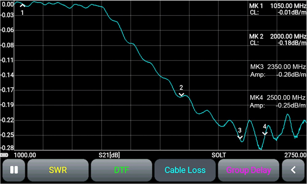
- Measure attenuation in the cable
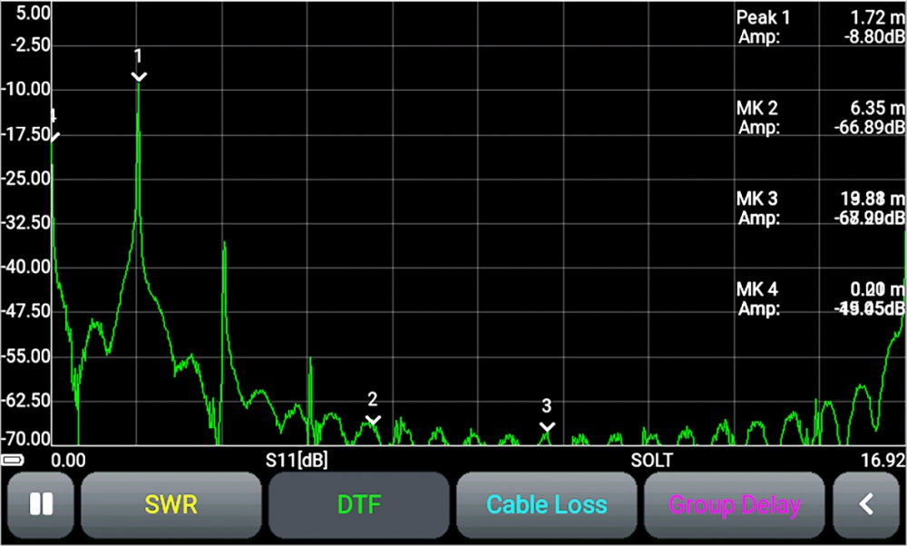
- Measure the distance to damage in the cable or its length
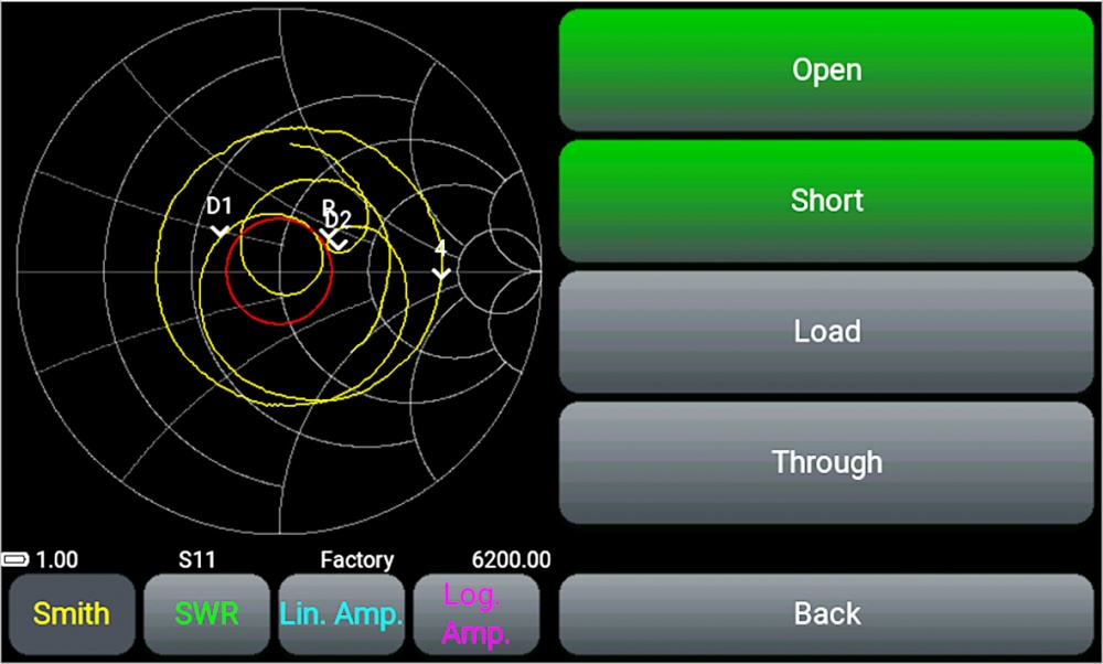
Attention! All devices are calibrated by the manufacturer. Removable SMA adapters screwed onto the device connectors are taken as the reference plane. When using cable assemblies or additional adapters, the device must be recalibrated according to the instructions. To calibrate the instrument, we recommend using ready-made calibration kits with N-type и SMA-type connectors.
To avoid premature wear of the instrument connectors, we recommend taking measurements with the screw-on adapters supplied.
The advantages of the ARINST VNA-PR1:
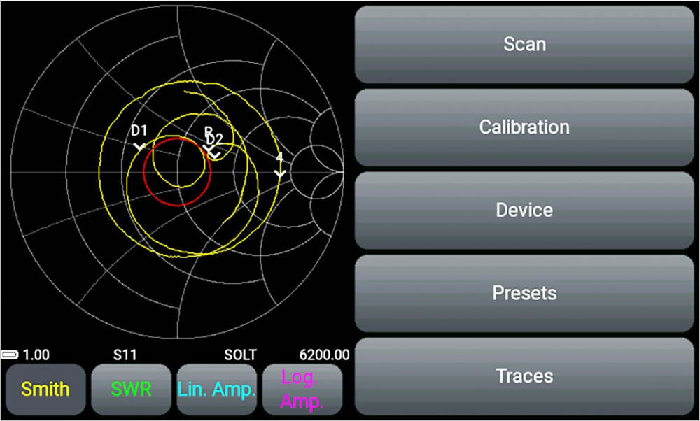
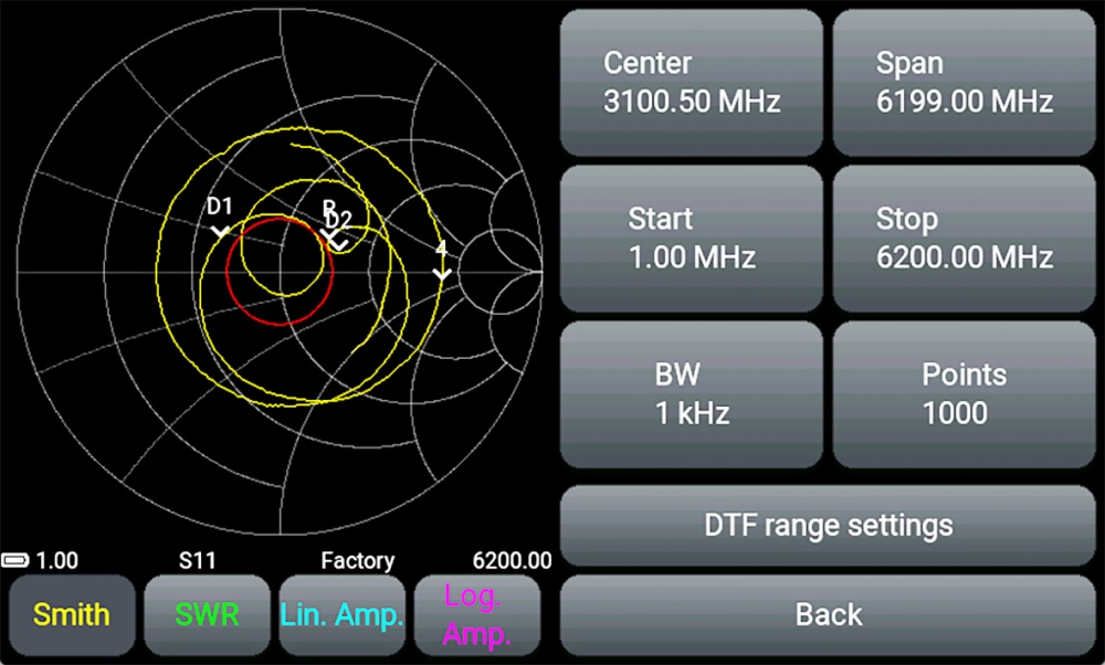
- a 4-inch color touch screen allows you to quickly configure scanning parameters and display measurement results
- simple and intuitive on-screen interface of the device
- wide range of operating frequencies: from 1 to 6200 MHz
- high scanning speed - 1000 points / s
- low error of reflection coefficient measurement: 0.25 dB and 0.7° over the entire frequency range
- adjusting the output power of the probe signal generator
- the ability to display up to four independent markers on all graphs, allowing an accurate assessment of the measured parameter
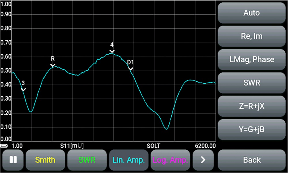
- displaying almost all possible interpretations of the reflection coefficient
- saving 32 user presets and 32 measurement results – traces
- setting the SWR threshold line for Smith, Polar, SWR, and Log charts. Amp (in S11 measurement mode)
- ability to measure the distance to damage and loss in the cable
- ability to compensate for the electrical length of the cable
- shift of the amplitude scale when measuring the frequency response of active devices and attenuators
- low weight and dimensions: 400 grams with "pocket" dimensions 150 × 81 × 27 mm
- intelligent system for determining the maximum charging current depending on the power source
- built-in battery capacity of 5000 mAh provides up to 2.5 hours of autonomous operation of the device
| Technical characteristics of ARINST VNA-PR1 | |||
| Operating frequency range | 1-6200 MHz | ||
| Input connectors | SMA(female) | ||
| Frequency resolution | for frequencies 1-100 MHz | 100 Hz | |
| for frequencies 100-6200 MHz | 10 kHz | ||
| Maximum number of scan points | 1000 | ||
| Scan speed | 1000 points / s | ||
| Dynamic range S21 (BW=250 Hz) | for frequencies 1-1,5 MHz | > 60 dB type.70 | |
| for frequencies 1,5-4500 MHz | > 80 dB type.90 | ||
| for frequencies 4500-6200 MHz | > 70 dB type.75 | ||
| The directivity of the bridge is unadjusted over the entire range | > 12 dB | ||
| Directivity effective1 (after full one-port calibration) | > 55 dB | ||
| Input standing wave ratio | < 2 | ||
| Phase measurement error1 | < 0,7° | ||
| Magnitude measurement error 1 | < 0,25 dB | ||
| Resolution for determining the distance to fault2 | (C x VF) / 2S m | ||
| Maximum length of the measured cable3, when VF=1 | 3000 m | ||
| Compensation electrical length of the cable, when VF=1 | ±3 m | ||
| Maximum DC Input Voltage | 25 V | ||
| Maximum input power supplied to the ports | + 10 dBm | ||
| Maximum power of the probing signal4 | < -5 dBm | ||
| Displayed charts | Smith chart; polar chart; phase of the reflection coefficient S11 and transmission coefficient S21 ; magnitude of S11 and S21; logarithmic magnitude of S11 and S21; SWR; distance to fault; cable loss, group delay. | ||
| The number of user settings to remember | 32 | ||
| The number of traces to remember | 32 | ||
| Working temperature range | 0 ... +40оС | ||
| Screen diagonal | 4" | ||
| Screen type | touch, resistive | ||
| Screen resolution | 800 х 480 | ||
| Maximum current consumption | when charging the battery | ≤ 2 А5 | |
| when running on battery | ~ 1 А | ||
| when using USB with battery charging6 | ≤ 2 А5 | ||
| Battery capacity | 5000 mAh | ||
| Time of continuous battery life7 | 2,5 h | ||
| Battery charge time5 | ~ 3,5 h | ||
| Overall dimensions (L × W × H) | 150×81×27 mm | ||
| Weight | 0.4 kg | ||
1 The measurement is performed after warming up the instrument for at least five minutes with a full calibration. The change in ambient temperature from the moment of calibration to measurements should not exceed ± 3 ° С.
2 Where C is the speed of light m/s; VF – velocity factor (the ratio of the speed of propagation of electromagnetic waves in the cable to the speed of propagation of electromagnetic waves in a vacuum), takes a value from 0.1 to 1 (depending on cable); S - scanning frequency range (Hz).
3 Depends on the amount of attenuation in the cable and is the indication limit on the display.
4 With the possibility of reducing.
5 When connecting the device to a charger with an output current of at least 3A.
6 If your PC has a limit on the maximum current supplied to the USB port, the device will automatically limit the maximum charging current according to the current USB specification.
7 At an ambient temperature of 20±5°C after the battery is fully charged.
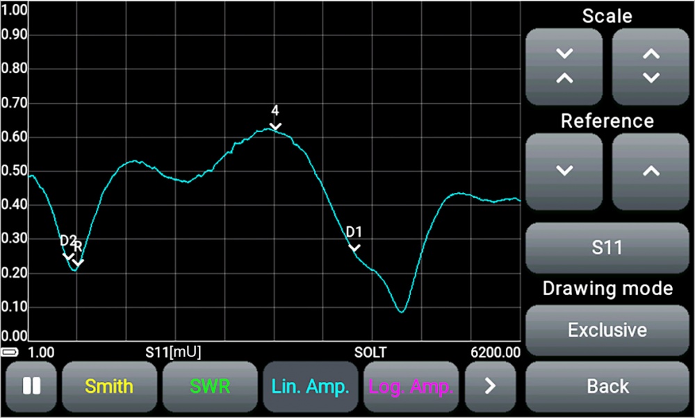
Screen interface of the device
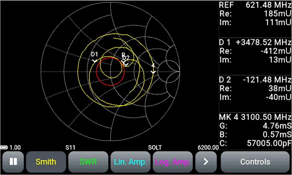
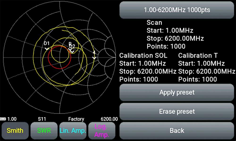
Charts and plots
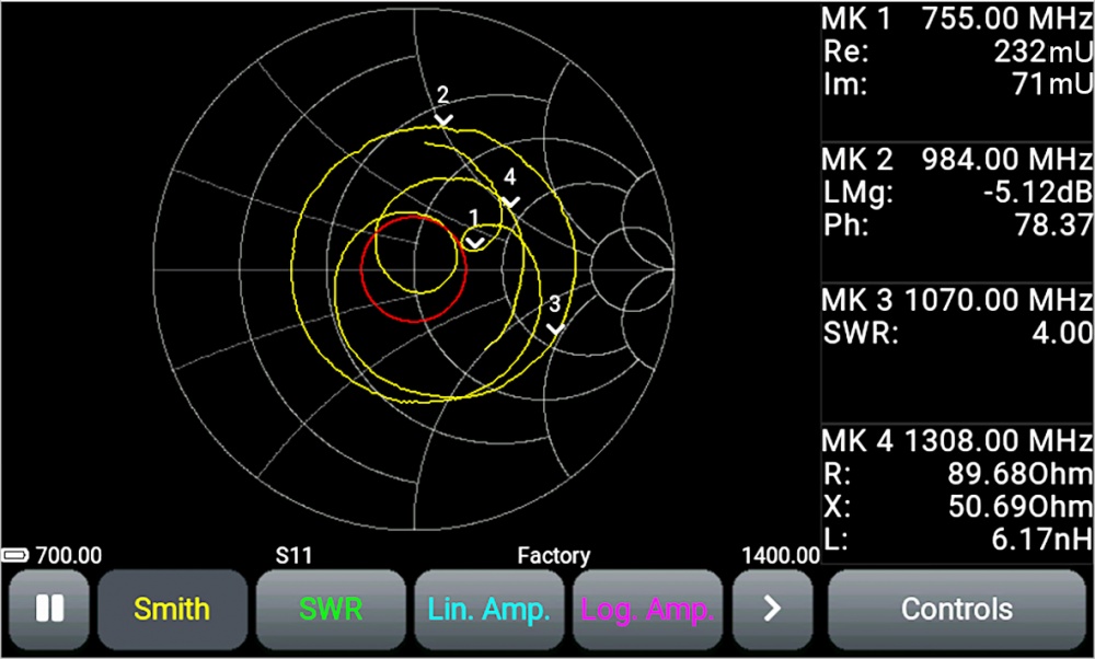
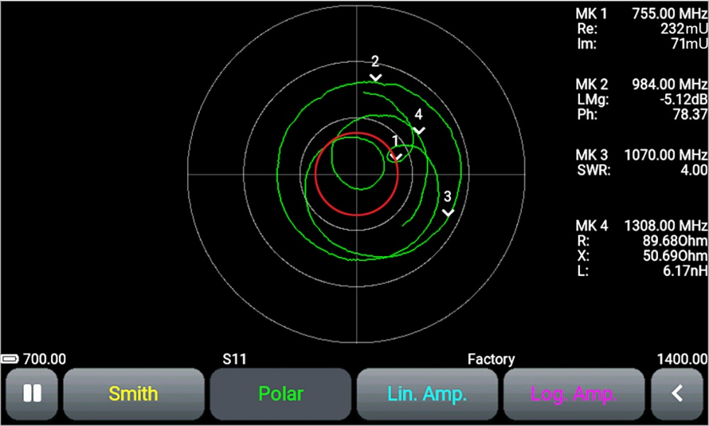
Smith diagram and polar chart
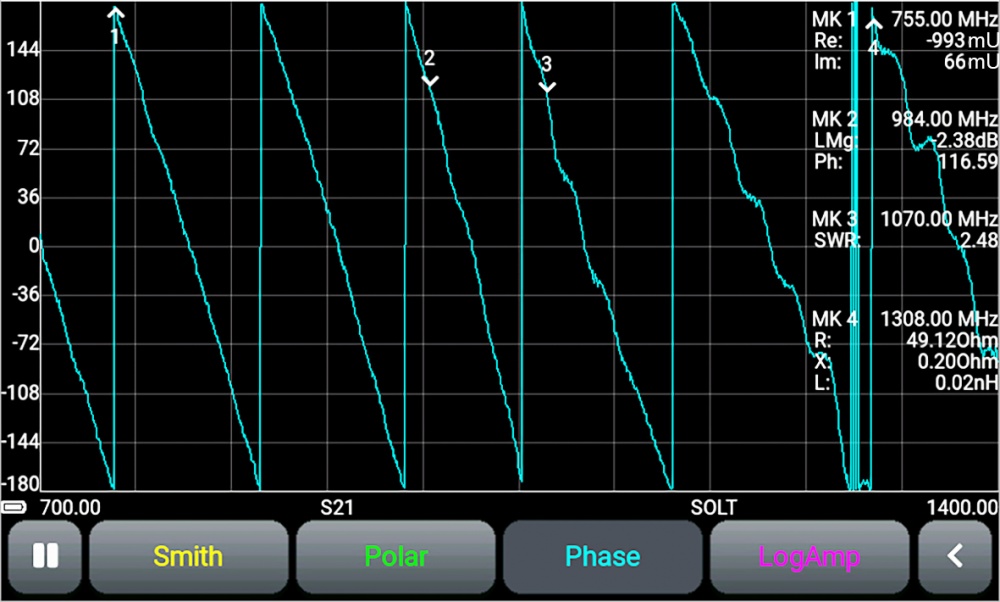
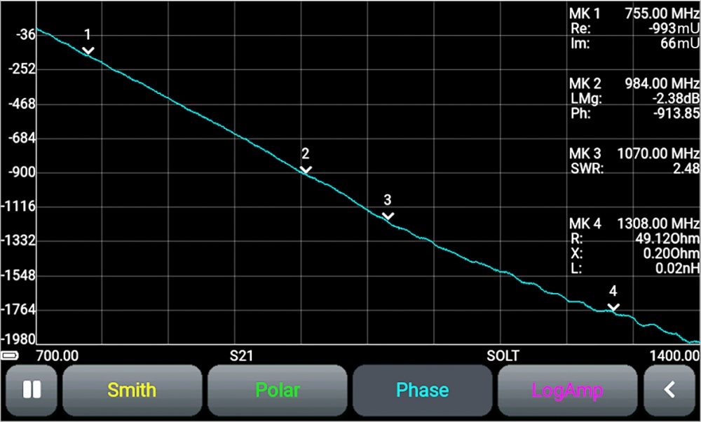
Phase plot in measurement mode S21 and Plot of the unwrapped phase in the S21 measurement mode
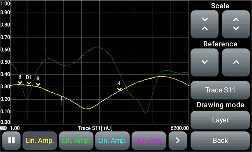
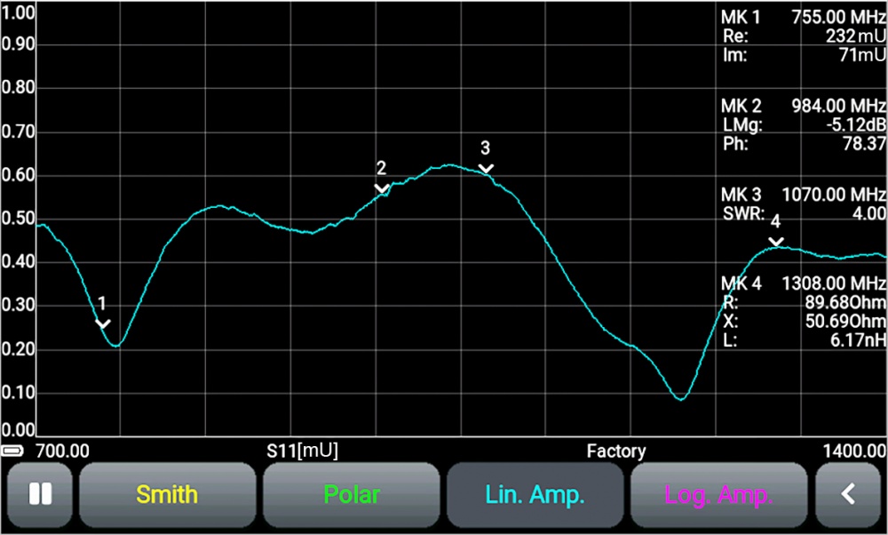
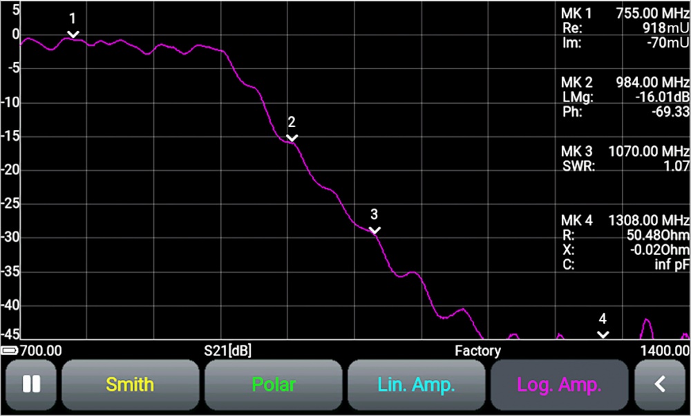
Linear plot of the magnitude (mode S11) and Logarithmic plot of the magnitude (mode S21)
VSWR plot and plot of distance measurement to cable fault
Plot of cable loss measurements and Group delay plot
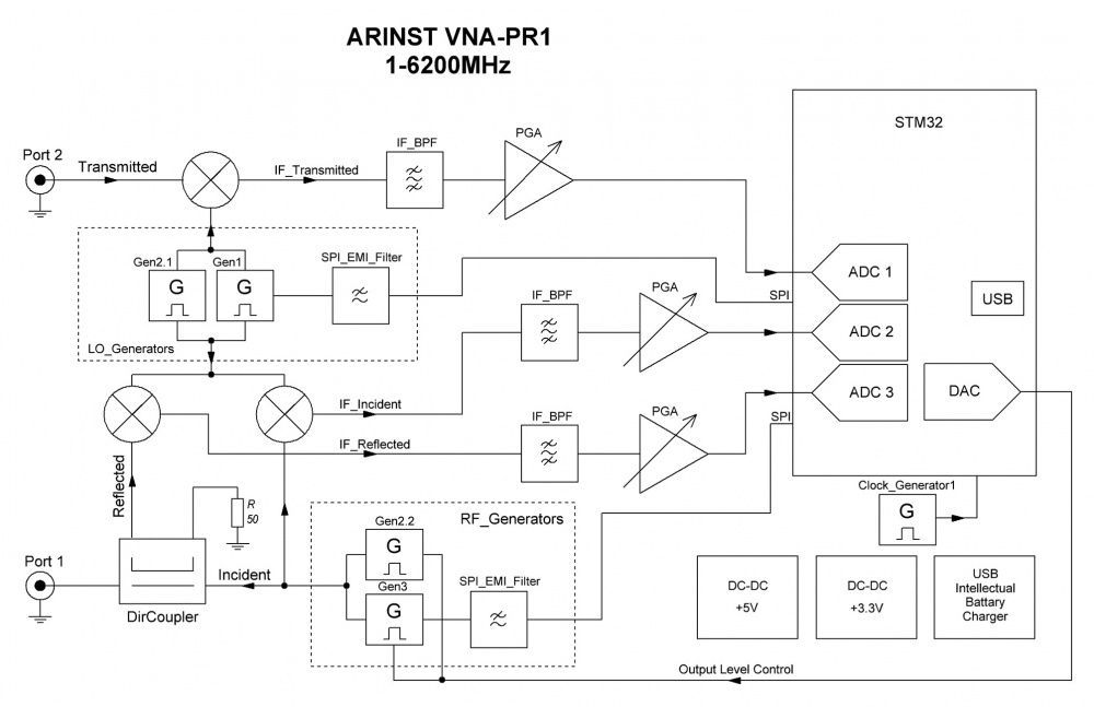
Block Diagram of the ARINST VNA-PR1 1-6200 MHz
|
Dimensions (length , width , height ), mm
|
150
x
81
x
27
|
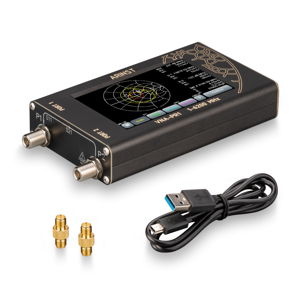
Equipment:
|
Position
|
Device
|
|
Cable mini-USB(male) to USB2.0(male)
|
||
|
Adapter SMA(female)-SMA(female) to protect connectors from wear
|
||
|
User manual
|
||
|
Packaging
|
||